1.Idea progression:
Midterm is during Halloween, so my partner Shivani had an idea of a Spooky photo booth with some sensor (TBD) that triggers webcam to take spooky distorted pictures. We started brainstorming by asking ourselves what kind of activities we would want our users to engage at the photo booth without giving explicit instructions or without them knowing what they need to do in order to create surprises and fun. I told Shivani about my experience playing with the mood ring the other day. As I put on the ring the color of the stone on the ring changes depending on my finger temperature and each color represents a mood. So I thought of implementing some wearables that output some individualized messages, that could be fortune or curses, depending on the attributes of the person wearing. Shivani instantly thought about the sorting hat from Harry Potter. That was a moment of excitement when we realized we can have a fancy fortune-telling witch hat as a prop for triggering the camera at the photo booth.
2. Picking sensors:
When picking sensors, we were considering an analog sensor that outputs individualized messages and a digital sensor that triggers the webcam to take pictures. Our options are:
Temperature sensors to sense forehead temperature - but it's slow reacting and people’s forehead temperatures don't vary as much by individual.
Distance sensor/flex sensor inside top of the hat to detect the depth of hat worn
FSR sensor on the rim to sense how tight the hat is worn
However, since these analog readings all depend on the wearer’s head size, the implementation of these sensor values is not as intuitive. So we were rethinking: why do we want to get head sizes? How are different head sizes related to messages? What’s the relationship? What kind of messages do we want to give users and how are they individualized?
At this point, we also thought about an accelerometer which changes readings on different axis depending on the tilting motion of the hat on the head.
After going through our ideas at a meeting with resident Mithru, we decided that instead of mapping analog readings to the messages, we would just have the messages generated randomly by a digital sensor, either a button or an LDR that also triggers the webcam, and have an accelerometer to control the values of image distortion, based on the motion of the hat on wearer's head. The result would be instant to notice as the users would understand what the hat does without any explicit instructions when they put it on. Another proposition we had during the meeting was using a Bluetooth module to wirelessly connect the sensors with the computer because having wires coming out of the hat could be annoying and hard to manage. However, Mithru and Luisa later in class both suggested us to start working with wired circuit first because Bluetooth is tricky to work with and sometimes and there might be some interference causing uncertainties.
In week 7’s class where we discussed our project ideas, our classmate Chunhan suggested that we could use a capacitive sensor as a touch sensor, where skin contact of the hat triggers the webcam, just like her apple piano project, and we thought this would be a suitable option for our project.
3. Testing the sensors/set up the circuits:
Up to this point, we had a solid design model in our head, the next step would be implementing the idea by setting up the circuits and writing the code.

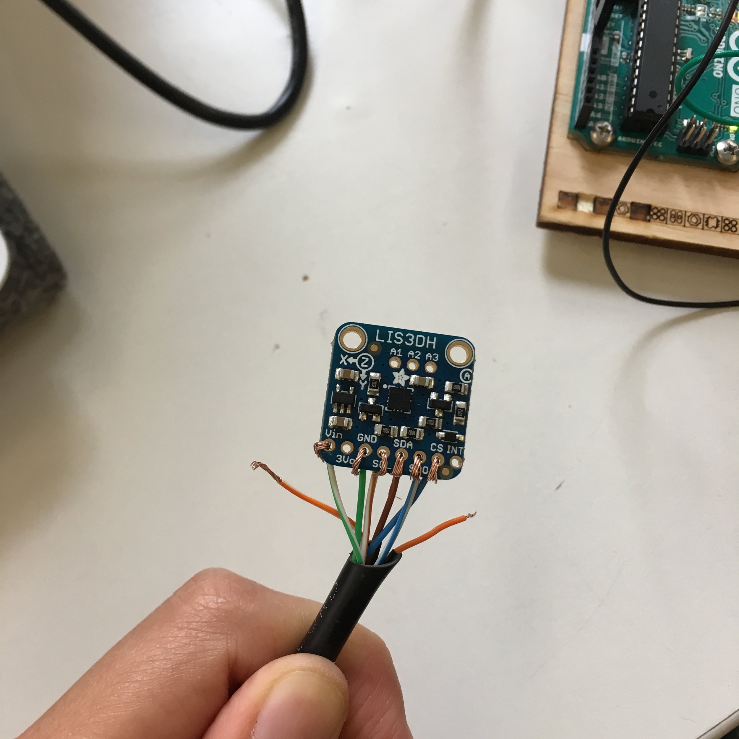
We checked out an Adafruit LIS3DH Triple-Axis Accelerometer from the shop and looked at the Datasheet. There were 8 pins on the sensor. We were confused at what each one does. On the datasheet, there are also two different types of wiring: SPI and I2C. So we did some research here on the differences between SPI and I2C and here on the function of pins and decided that we should use SPI wiring given some of its advantages over I2C explained in the article. We then wired the circuits and downloaded the libraries needed for the accelerometer. When we ran the "Acceldemo" example code, we got the sensor readings on all XYZ axis and decided that we are only interested in the converted values in m/s^2 (range -10 to 10) being that the raw data set had a range too big to work with.

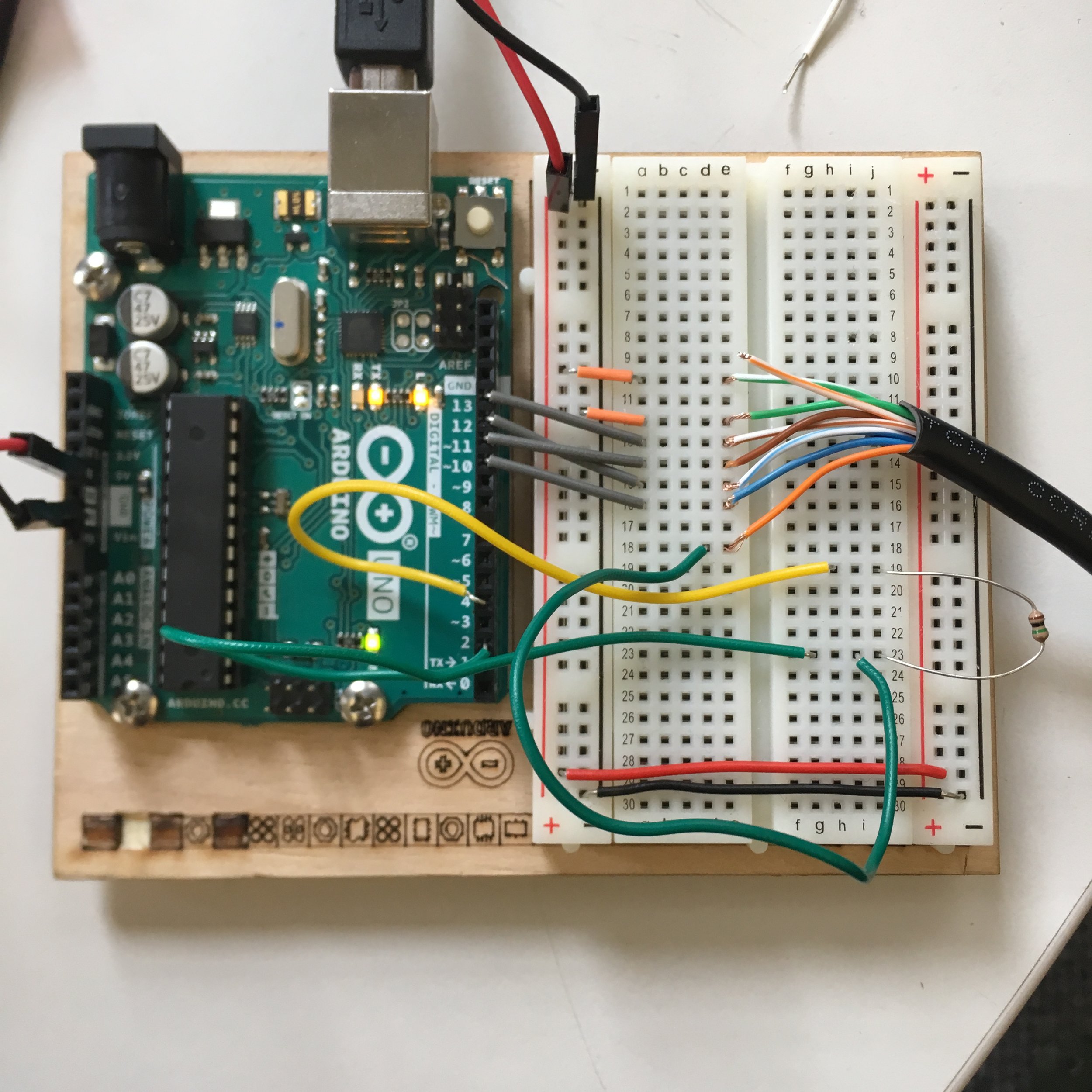
For the capacitive sensor, we referred to Chunhan's apple piano blog post and the arduino documentation. We downloaded the capacitive sensor library and tested the sensor with the "CapacitiveSensor" example code. We used a 1 megohm resistor because according to the documentation, 1 megohm resistor or less works the best for absolute touch to activate. It also suggests "A wire connected to this pin with a piece of foil at the end makes a good sensor. For many applications, a more useful range of values is obtained if the sensor is covered with paper, plastic, or another insulating material so that users do not actually touch the metal foil. " So we set up the circuit like the picture below and connected the open wire end with a piece of foil and paper on top. We found out that the sensor reading is generally below 100 if there's no skin contact, and goes over 100 with a light touch, and up to 10000 with some pressure applied. So we decided to map all the readings below 100 as 0 and above 100 as 1 to treat it as a digital input to detect if the wearer's forehead is touching the hat or not.


Schematic
4. Serial communication test with P5:
After testing the sensors, we altered the Arduino example codes for accelerometer and capacitive sensor separately and used the accelerometer readings x y z to draw red green and blue colors of 3 ellipses separately and have the touch sensor to draw a square on the sketch. Once we got individual sensors to work, we combined the codes for both sensors and used duplex serial communication and serial handshaking to request and receive data of all sensor readings between p5 and Arduino:
accelerometer + touch sensor Arduino test code:
//human capacitor /* 1 megohm resistor between pins 4 & 2, pin 2 is sensor pin, add a wire and or foil if desired*/ #include CapacitiveSensor cs_4_2 = CapacitiveSensor(4, 2);
//accelerometer #include #include #include #include
// Used for software SPI #define LIS3DH_CLK 13 #define LIS3DH_MISO 12 #define LIS3DH_MOSI 11 // Used for hardware & software SPI #define LIS3DH_CS 10
// hardware SPI Adafruit_LIS3DH lis = Adafruit_LIS3DH(LIS3DH_CS);
int x, y, z; void setup() { #ifndef ESP8266 while (!Serial); // will pause Zero, Leonardo, etc until serial console opens #endif
Serial.begin(9600);
Serial.println("LIS3DH test!");
if (! lis.begin(0x18)) { // change this to 0x19 for alternative i2c address Serial.println("Couldnt start"); while (1); } Serial.println("LIS3DH found!");
lis.setRange(LIS3DH_RANGE_2_G); // 2, 4, 8 or 16 G!
Serial.print("Range = "); Serial.print(2 << lis.getRange()); Serial.println("G");
//serial handshaking while (Serial.available() < 0) { Serial.println("hello"); // send a starting message delay(300); // wait 1/3 second } } void loop() { //capacitor: long cap = cs_4_2.capacitiveSensor(30); int touch = 0; if (cap > 100) { touch = 1; } else { touch = 0; } // Serial.println(touch); // Serial.println(cap); // print sensor output 1
//accelerometer: lis.read(); // get X Y and Z data at once
sensors_event_t event; lis.getEvent(&event);
/* convert the results (acceleration is measured in m/s^2) to a range of 0 -200 integers */ x = int(100 + 10 * event.acceleration.x); y = int(100 + 10 * event.acceleration.y); z = int(100 + 10 * event.acceleration.z); // Serial.println(touch); //serial handshaking if (Serial.available() > 0) { // read the incoming byte: int inByte = Serial.read(); //read sensors Serial.print(x); Serial.print(","); Serial.print(y); Serial.print(","); Serial.print(z); Serial.print(","); Serial.println(touch); } delay(200); }
serial communication P5 test code: https://editor.p5js.org/ada10086/sketches/HygLzdIsX
5. P5 photobooth sketch
In the process of programming the photo booth in P5, we saw this transparency example in p5 reference and were inspired to create ghost/monster filters on top of the image capture and have the accelerometer reading x and y (hat movement) to control the movement of the filters relative to the center of the canvas.
We first programmed a photo booth without serial communication, with only the buttons to take the pictures and reset the camera, and have the ghost filters jiggle randomly around the center.
P5 code: https://editor.p5js.org/ada10086/sketches/rksofdUim

6. Using sensors to control P5 photo booth sketch
The next step was to combine the sensors with our p5 photo booth sketch. Our biggest challenge in this step was to figure out the code for countdown once touch sensor is touched (hat is on touch = 1) and reset the webcam back to active once touch sensor is released (hat is off touch = 0). The original photo booth controlled by the button with a mousePressed function works a bit differently from the booth controlled by a touch sensor, which changes between 1 and 0, therefore we had to keep track of the state change of the touch sensor the moment the hat is put on (from 0000 to 1111) and the moment the hat is taken off ( from 11111 to 00000).
Arduino final code:
//human capacitor /* 1 megohm resistor between pins 4 & 2, pin 2 is sensor pin, add a wire and or foil if desired*/ #include CapacitiveSensor cs_4_2 = CapacitiveSensor(4, 2);
//accelerometer #include #include #include #include
// Used for software SPI #define LIS3DH_CLK 13 #define LIS3DH_MISO 12 #define LIS3DH_MOSI 11 // Used for hardware & software SPI #define LIS3DH_CS 10
// hardware SPI Adafruit_LIS3DH lis = Adafruit_LIS3DH(LIS3DH_CS);
int x, y; void setup() { #ifndef ESP8266 while (!Serial); // will pause Zero, Leonardo, etc until serial console opens #endif
Serial.begin(9600);
Serial.println("LIS3DH test!");
if (! lis.begin(0x18)) { // change this to 0x19 for alternative i2c address Serial.println("Couldnt start"); while (1); } Serial.println("LIS3DH found!");
lis.setRange(LIS3DH_RANGE_2_G); // 2, 4, 8 or 16 G!
Serial.print("Range = "); Serial.print(2 << lis.getRange()); Serial.println("G");
//serial handshaking while (Serial.available() < 0) { Serial.println("hello"); // send a starting message delay(300); // wait 1/3 second } } void loop() { //capacitor: long cap = cs_4_2.capacitiveSensor(30); int touch = 0; if (cap > 100) { touch = 1; } else { touch = 0; } // Serial.println(touch); // Serial.println(cap); // print sensor output 1
//accelerometer: lis.read(); // get X Y and Z data at once
sensors_event_t event; lis.getEvent(&event);
/* convert the results (acceleration is measured in m/s^2) to a range of -10 - 10 integers */ x = int( event.acceleration.x); y = int( event.acceleration.y); // Serial.println(touch);
// serial handshaking if (Serial.available() > 0) { // read the incoming byte: int inByte = Serial.read(); //read sensors Serial.print(x); Serial.print(","); Serial.print(y); Serial.print(","); Serial.println(touch); } delay(200); }
Final P5 code: https://editor.p5js.org/ada10086/sketches/H13xgRDj7
7. Wiring:
As shown in the system diagram, we decided to place the sensors inside the hat, and have Arduino board outside with computer. We have 7 wires connected to the sensor which come out from the hat, wire management was the biggest challenge for us.

IMG_8205
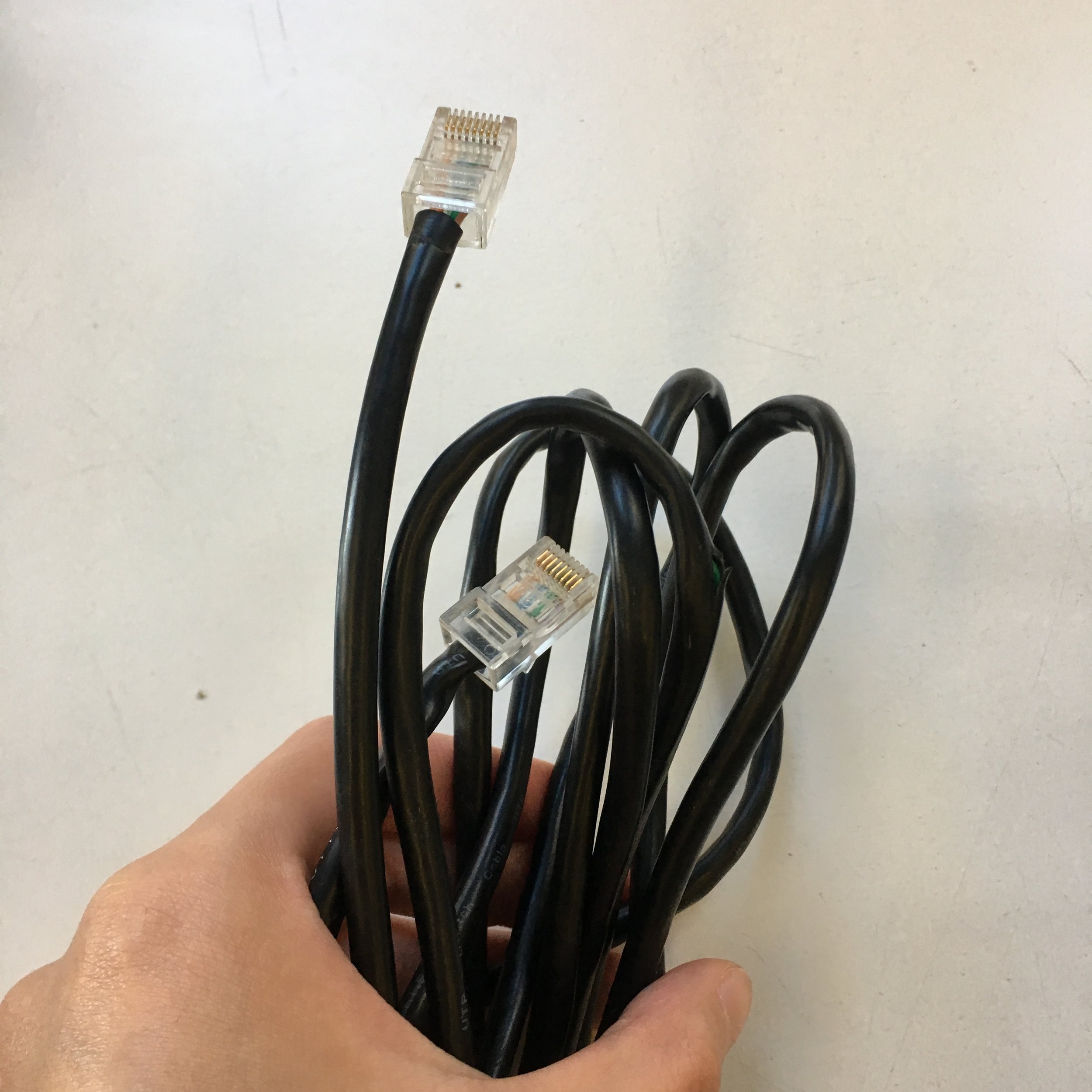
I learned in my light arts club that ethernet cable is a good cable management strategy. Inside each cable, there are 8 thin wires wrapped together. Therefore, instead of 8 separate cables hanging around, there's only one visible cable, and it's flexible enough to allow the hat to move around. However, when we connected everything, the touch sensor was working but we could never get the readings from the accelerometer.
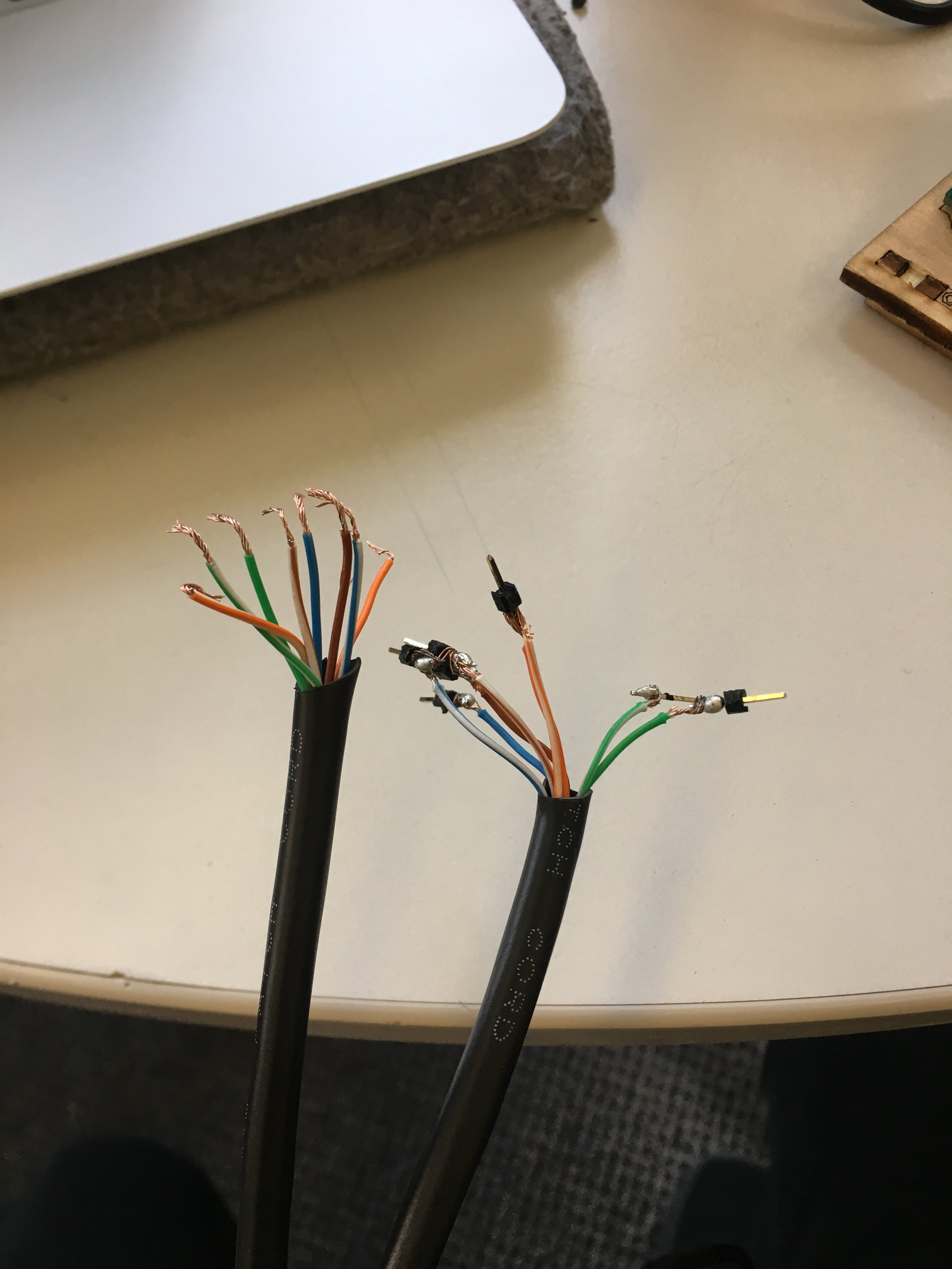
We decided to try out stranded core wire, which is also flexible but much thicker, and we had to twist the wires together because they were separate, so we tied two ends and used a drill to twist them. However, after we twisted them we realized that there was no way to distinguish which wire comes from which pins of the sensors because they are not color coded like the ethernet wires, so we had to untwist them again and label each wire with a number, which was a very messy and redundant process. As we connected the programs, the same issue persisted as with the ethernet cable, and we couldn't figure out where the connection went wrong.
We believed that because each stranded core wire and individual thin wire inside ethernet cables are both made of many very thin and fragile "hairs" that break easily and very hard for alloys to stay during solder, this could also potentially cause our circuits to break or disconnect easily during transportation and experimentation.
stranded core wire
Therefore, we decided to go with the traditional wire-wrap wire, which is very stiff and could weight the hat down and drag the Arduino board around when the hat is moving. However, an advantage of the stiffness is that we do not need to solder header pins on the other ends of the wires and it is able to horizontally hold the accelerometer inside top of the hat in place without having to tape or sew the actual sensor onto the hat, and we would be able to attach and remove the sensor from the hat easily.

stranded core wires

wire-wrap wire

Assembly materials
8. Assembly
We bought a hat from a Halloween store and were ready to assemble the sensors with the hat. We grabbed some conductive materials from the soft lab: copper tape, conductive fabric, as well as velcro, sewing kit, tapes, fabric glue and alloy.
We tried conductive fabric, it was not as responsive, the value only changed significantly when there was a press instead of a touch, and the further we went down the wire, the less responsive. So we decided to try out the copper tape.
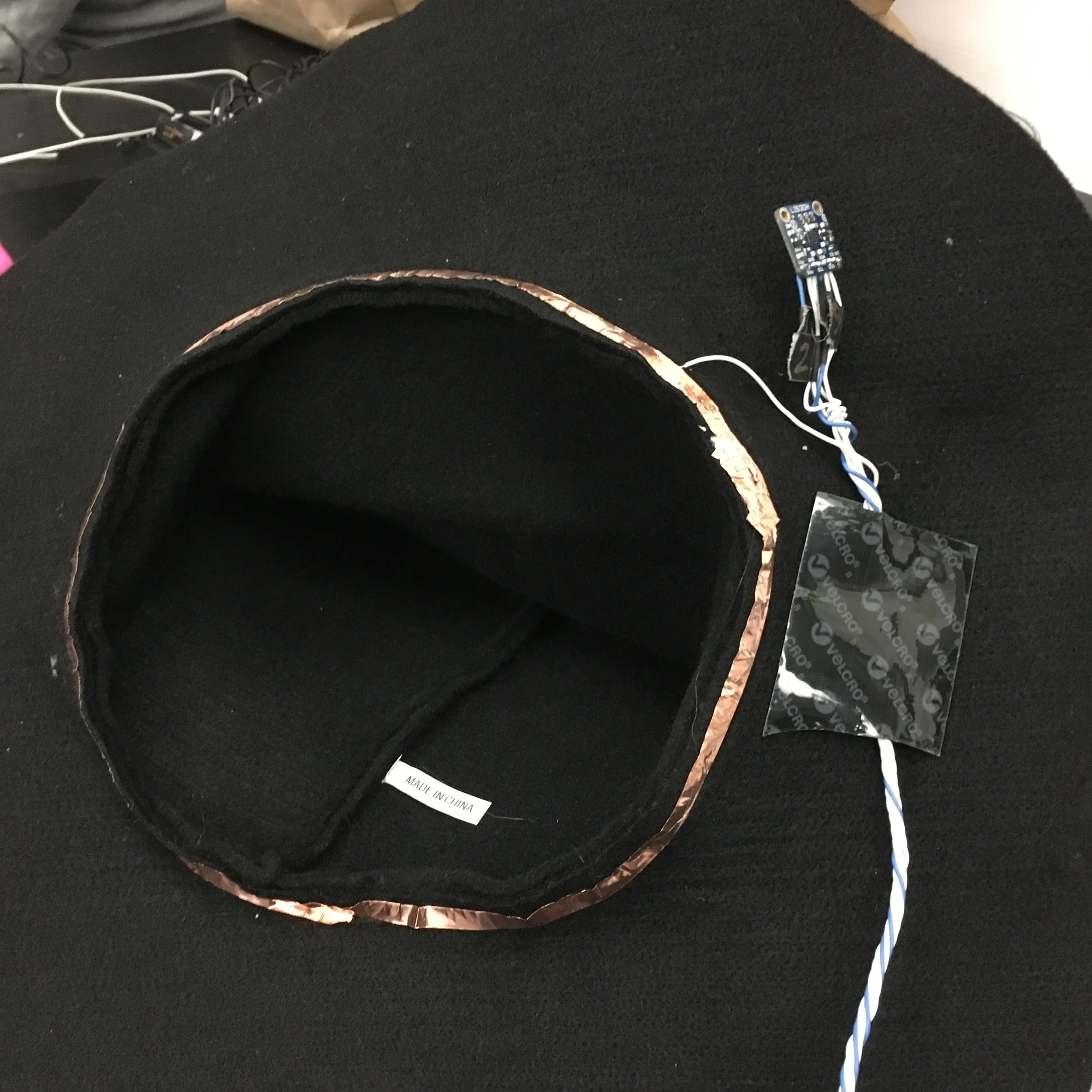
Our attempt was to have the copper tape attached to the touch sensor and circled it around the inside rim of the hat and have the accelerometer attached under the hat rim. The result was very unpredictable. When we print the touch sensor readings on the serial monitor, the moment the hat is put on or off, the readings were not as clean as we expected from 11111 to 0000 or 00000 to 11111. Instead, it was jumping between 1 and 0 at the instant of hat on or off. We thought it might be because there were too many contact points on the copper tape around the hat and there are many small contacts happening during the action of putting the hat on and taking it off.
Therefore, we tried folding a piece of foil and coiled up some alloy which was attached to the wire wrap wire and placed in between the two sides of the foil to make sure everything was in firmly contact with each other by taping some copper tape on top. And we stuck up the accelerometer all the way up to the inside of the hat and held the wires in place with a big piece of velcro. Having the wire wrap wires coming straight down from the hat instead of coming out sideways avoided the problem of stiff wires weighing the hat down and tilting the accelerometer by default, which could mess with the sensor readings on x and y axis.
Hat assembly 1

Hat assembly 2

Hat assembly final
And finally, we had a working photobooth!
Demo: