
Digital Output - blinking LED

Digital input 1 - press button to turn off LED

Digital input 2 - press button to switch on red and yellow LEDs alternatively and change the blinking speed of green LED

Analog input - press button to blink LED, turn potentiometer to change blinking speed


Application: analog input from temperature sensor to indicate whether water is cool enough to drink. As shown in the videos below, when the temperature sensor is attached to a cup of water at 30 degree Celsius, green LED is lit, indicating ok to drink; when sensor gets close to a cup of hot water >57 degree celsius (I picked the value from a study which claims the optimal drinking temperature of hot drink is 57), red LED is lit, indicating it's too hot to drink. Of course the temperature threshold here is arbitrary, I can adjust the value to whatever I want.

W3 Application schematic

W3 Application

W3 Application
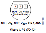
TMP36 temperature resistor properties:

I picked a temperature sensor over a thermistor because I read here that a temperature sensor outputs a voltage which has a linear relationship with temperature, therefore easier to do the conversion, whereas a thermistor's resistance and temperature has a exponential relationship.
According to tmp36 data sheet: Both the TMP35 and TMP36 have an output scale factor of 10 mV/°C(0.01V/°C). It is a linear relationship between output voltage and temperature. When output voltage is 0, temperature is -50°C, therefore when calculating temperature from analog reading, it needs a -50 offset.
set sensorValue to analogRead(A0)
output voltage V = sensorValue*5V/1024
therefore, relationship between temperature and sensorValue:
t = V / (0.01V/°C) - 50°C offset = (sensorValue *5V / 1024 ) / (0.01V/°C) - 50°C
When t value is printed on serial monitor, simple electronic thermometer is created.
Challenge:
I was having trouble getting the correct temperature reading even my conversion calculation was correct. The temperature reading turned out to be very off the realistic value(150-200), and my temperature sensor would heat up so fast and almost too hot to touch. After googling possible issues, I found out that the pin configuration on the data sheet was incorrect, and I found the correct configuration on Adafruit.
2. In order to get the sensor close to water cups, I have to extend the component by soldering wires on each pins. So I attempted soldering. With some soldering experience in the past, I successfully soldered the first sensor, but the middle pin fell off during transfer, so I had to re-solder everything again with a new sensor. Seems like the pins are very easy to break.
3. the application isn't that useful in real life because the change in temperature reflected in change in output voltage is not instant, so it takes time for the LEDs to react even when the temperature already passes a value.